|
|
|
|
The telephone system is tightly intertwined with (wide area) computer networks, so it is worth to study it.
Public Switched Telephone Network (PSTN), that is used today also for computer networking, was designed many years ago with a completely different goal in mind: to transmit the human voice in a more or less recognizable form. Its suitability for use in computer - computer communication is often marginal at best, but the situation is rapidly changing with the introduction of fibre optics and digital technology.
An example illustrating the magnitude of the problem: Comparing a standard
error rate of the cable connection of two computers running at memory
speeds (107 to 108 bps), say 1 error per day, with the standard error
rate when the computers communicate through a dial-up line at
104 bps, that is about 1 per 105 bits sent, we get difference about 11 orders.
2.4.1. Structure of the Telephone System
The telephone was patented by Graham Bell in 1876. Initially, the telephones were sold in pairs and it was up to customer to string a single wire between them. The electrons returned through the earth.
Bell formed also the Bell Telephone Company which opened its first switching office in New Haven, Connecticut, in 1878. To make a call, the customer would crank the phone to ring in the telephone company office where the operator manually connected the caller to the callee using a jumper cable. (Fig. 2-14(b)).
Later, the switching offices had to be connected to make long-distance calls possible. Therefore second-level switching offices became necessary (Fig. 2-14(c)) and successively the hierarchy grew to five levels. This scheme remained essentially intact for over 100 years.

Fig. 2-14. (a) Fully interconnected network. (b) Centralized
network. (c) Two level hierarchy.
At present, the telephone system can be, with some simplifications, described as follows: Each telephone has two copper wires coming out of it that go directly to the telephone company's nearest end office (in the US there are about 19000 end offices). The two wire connection of the telephone and end office is called local loop.
If a subscriber attached to a given end office calls another subscriber attached to the same end office, the switching mechanism within the office sets up a direct electrical connection between the two local loops that remains intact for the duration of the call.
If a called telephone is attached to another end office, the path will have to be established somewhere higher up in the hierarchy. There are toll offices, primary, sectional, and regional offices that form a network by which the end offices are connected. They communicate with each other via high bandwidth interoffice trunks formed today by coaxial cables, microwaves and especially fiber optics. The number of different kinds of switching centers and their topology varies from country to country depending on its telephone density (Fig. 2-15.)

Fig. 2-15. Typical circuit route for a medium-distance call.
In the past, signaling throughout the telephone system was analog. Now, all the long-distance trunks within the telephone system are rapidly being converted to digital using optical fibers. It has the following reasons:
In summary, the telephone system consists of three major components:
The local loops are sill analog. Consequently, when a computer wishes to send digital data over a dial-up line, the data must first be converted to analog form by a modem for transmission over a local loop, then converted to digital form for transmission over the long-haul trunks, then back to analog over the local loop at the receiving end, and finally back to digital by another modem for storage in the destination computer (Fig. 2-17.).
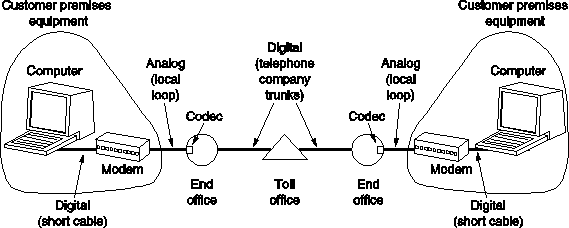
Fig. 2-17. The use of both analog and digital transmission
for a computer to computer call.
Conversion is done by the
modems and codecs.
For leased lines it is possible to go digital from start to finish, but
these lines are still expensive.
2.4.3. Transmission Impairments
Transmission lines suffer from three major problems:
Due to transition impairments dependent on frequency, it is undesirable to have a wide range of frequencies in the signal. Square waves of digital data have a wide spectrum and thus are subject to strong attenuation and delay distortion. So the baseband (DC) signaling is unsuitable except at slow speed and over short distances.
To get around the problem, especially on telephone lines, analog (AC) signaling is used. It is based on continuous tone in the 1000 to 2000 Hz range, called sine wave carrier, with amplitude, frequency or phase modulation to transmit information (Fig. 2-18.).
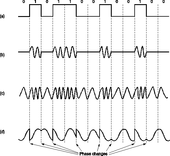
Fig. 2-18. (a) A binary signal. (b) Amplitude modulation.
(c) Frequency modulation. (d) Phase modulation.
In amplitude modulation, two different voltage levels are used to represent 0 and 1, respectively.
In frequency modulation (or frequency shift keying), two or more different tones are used.
In phase modulation, the carrier wave is systematically shifted at uniformly spaced intervals. E.g., if 45, 135, 225, or 315 degrees shifts are used, each phase shift transmits 2 bits of information.
A device that accepts a serial stream of bits as input and produces a modulated carrier as output (and vice versa) is called modem (for modulator-demodulator).
To go to the higher speeds, it is not possible to just keep increasing the sampling rate. The Nyquist theorem says that even with the perfect 3000 Hz line there is no point in sampling faster then 6000 Hz. Thus all research on faster modems is focused on getting more bits per sample (i.e. per baud).
Most advanced modems use a combination of modulation techniques to transmit multiple bits per baud. 2 combinations of amplitude levels and phase shifts are displayed in Fig. 2-19. Such diagrams are called constellation patterns and each high-speed modem standard has its own one. The ITU V.32 9600 bps modem standard uses the constellation pattern of Fig. 2-19(b).
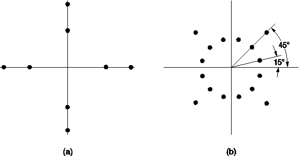
Fig. 2-19. (a) 3 bits/baud modulation. (b) 4 bits/baud modulation.
The next step above 9600 bps is 14400 bps (V.32 bis). This speed is achieved by transmitting 6 bits per sample at 2400 baud. Its constellation pattern has 64 points. After V.32 bis comes V.34 running at 28800 bps.
Many modems now have compression and error correction built into the modems. It improves the effective data rate. One popular compression scheme is MNP 5, which uses run-length encoding to squeeze out runs of identical bytes.
Full-duplex transmission. i.e. transmission in both directions at the
same time is based on the use of different frequency bands for each
direction. The alternative is half-duplex transmission, in which communication
can go either way, but only one at a time.
2.4.5. RS-232-C and RS-449
The interface between the computer and the modem is an example of a physical layer protocol. It must specify in detail the mechanical, electrical, functional and procedural interface. Two well-known physical layer standards are RS-232-C and its successor, RS-449.
RS-232-C is the third revision of the original RS-232 standard drawn up by the Electronic Industries Association (EIA). Its international version is given by CCITT recommendation V.24 and differs very slightly on some of rarely used circuits. In the standards, the terminal or computer is officially called DTE (Data Terminal Equipment) and the modem is officially called a DCE (Data Circuit-Terminating Equipment).
The mechanical specification is for a 25-pin connector 47.04+-.13 mm wide (screw center to screw center), with all the other dimensions equally well specified. The top row has pins numbered 1 to 13 (left to right); the bottom row has pins numbered 14 to 25 (also left to right).
The electrical specification for RS-232-C is that voltage more negative than -3 volts is a binary 1 and a voltage more positive than +4 volts is a binary 0. Data rates up to 20kbps are permitted, as are cables up to 15 meters.
The functional specification tells which circuits are connected to each of the 25 pins, and what they mean. Fig. 2-21 shows 9 pins that are nearly always implemented. The remaining ones are frequently omitted.
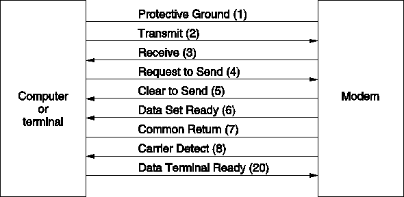
Fig. 2-21. Some of the pricipal RS-232-C circuits. The pin
numbers are given in parentheses.
The specification of some signals:
Other circuits are provided for selecting data rate, testing the modem, detecting ringing signal, etc. They are usually not used in practice.
The procedural specification is the protocol, that is, the legal sequence of events. The protocol is based on action-reaction pairs. When the computer asserts Request to Send, for example, the modem replies with Clear to Send, if it is able to accept data.
It commonly occurs that two computers must be connected using RS-232-C. Since neither is a modem, there is an interface problem. It is solved by connecting the computers with the device called null modem, which connects the transmit line of one machine to the receive line of the other. It also crosses some of the other lines in a similar way.
The successor of RS-232-C, RS-449, removes some of the limitations of
RS-232-C. Among them, it can be used at speeds up to 2Mbps and over 60
meter cables.
2.4.6. Fiber in the Local Loop
For advanced future services, such as video on demand, the 3-kHz channel currently used will not do. Two possibilities of what to do are discussed:
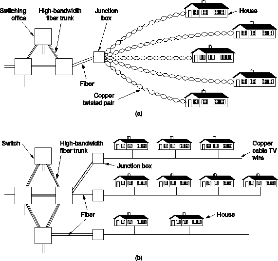
Fig. 2-23. Fiber to the curb. (a) Using the telephone network.
(b) Using the cable TV network.